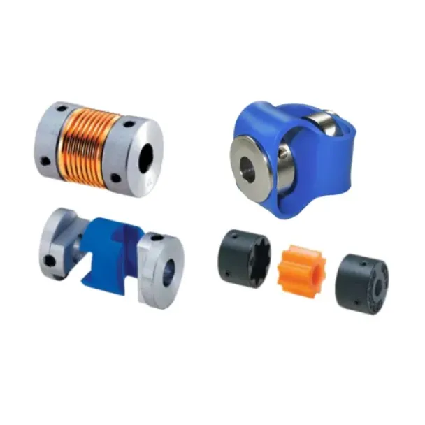
How to Select the Right Encoder Coupling for Your Application
An encoder is only as accurate as the connection between its shaft and the machine it measures. The coupling that joins them has to transmit rotation faithfully, absorb misalignment that would otherwise load the encoder bearings, and survive the shock, vibration and environment of the installation. Pick the wrong one and you get position errors, noisy signals or a failed encoder bearing.
Need help selecting an encoder coupling ? Send any questions through our contact page here, or call us directly on 1300 236 467
This guide explains what to look for when choosing an encoder coupling, compares the six PCA coupling series stocked in Australia, and gives a quick selection table so you can match a coupling to your application.
In this guide:
- What an encoder coupling does
- Five factors to consider when selecting a coupling
- PCA encoder coupling types compared (with specifications)
- Quick selection guide
- Installation tips
- Frequently asked questions
What does an encoder coupling do?
A solid-shaft encoder is connected to a motor or driven shaft with a flexible coupling. Shafts are never perfectly aligned, and they move during operation as the machine heats up and vibrates. A rigid connection would push those loads straight into the encoder's bearings. A flexible coupling takes up the misalignment instead, while staying stiff enough in rotation that the encoder sees exactly what the shaft does.
Unlike power-transmission couplings, encoder couplings carry almost no torque. What matters most is torsional stiffness (accuracy), misalignment capacity (bearing life) and fit (bore size and fastening).
5 factors to consider when selecting an encoder coupling
1. Torsional stiffness and backlash
Because an encoder measures rotation, any twist or play in the coupling shows up as measurement error. Torsional (static) stiffness, measured in N·m/rad, tells you how much the coupling resists twisting. For high-accuracy positioning, choose a zero-backlash coupling with high torsional stiffness, such as a bellows coupling. For speed feedback or general monitoring, a more flexible coupling is usually fine and absorbs more vibration.
2. Misalignment
Misalignment happens during installation (static) and during operation (dynamic, from heat, vibration and shaft movement). There are three kinds:
- Parallel offset (eccentricity): the shafts are parallel but not on the same centreline.
- Angular misalignment: the shafts meet at an angle.
- Axial movement (end play): the shafts move closer together or further apart.
Choose a coupling rated for the misalignment you expect. Exceeding the rating causes premature coupling failure and puts side loads on the encoder bearings.
3. Bore size and shaft combination
Measure both shafts. PCA couplings are available with matched bores (e.g. 10 mm to 10 mm) and mixed bores (e.g. 10 mm to 5 mm), covering 3 mm to 15 mm, with imperial 3/8" and 1/2" options in the CDL series. Also check the space between the shaft ends and the coupling's overall length and outer diameter.
4. Fastening method: set screw or clamp
- Set screw: low cost and compact. Best for light loads and where shafts have a flat to seat the screw.
- Clamp: grips the full circumference of the shaft, won't mark it, and holds better under vibration and reversing loads. Easier to remove and reposition.
PCA couplings use set screws as standard, with clamp hubs available as an option. The CJW jaw coupling is supplied with clamp hubs.
5. Material and operating environment
The environment drives the material choice. Aluminium hubs keep inertia and weight low. Stainless steel suits wet, washdown or corrosive areas. Polyurethane and polyacetal elements damp vibration and electrically isolate the encoder from the motor shaft, which helps prevent bearing currents and signal noise.
PCA encoder coupling types compared
How to read a PCA part number: series + outer diameter (mm) − bore 1 x bore 2 (mm). For example, COL25-10x05 is an Oldham coupling, 25 mm outer diameter, joining a 10 mm shaft to a 5 mm shaft.
CBR / CSS bellows couplings: zero backlash for high accuracy
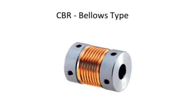
A metal bellows joins two hubs, giving zero backlash and high torsional stiffness while still flexing to absorb angular misalignment and axial movement. Bellows couplings are the first choice for high-resolution and precision positioning encoders.
- CBR: aluminium hubs, bronze bellows
- CSS: all stainless steel, for corrosive or washdown environments
- Static stiffness 110–330 N·m/rad; axial movement up to +0.6/−1.8 mm
- Keep parallel offset small: 0.1–0.15 mm max
COL Oldham couplings: large offset and electrical insulation
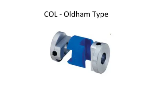
Two aluminium hubs drive a polyacetal centre disc that slides to take up large parallel offset with very low load on the shafts. The non-conductive disc electrically insulates the encoder from the driven shaft.
- Handles parallel offset up to 2.5 mm, the most of any PCA coupling
- Static stiffness 31–280 N·m/rad; rated torque 0.7–4.5 N·m
- Wide range of mixed-bore combinations (e.g. 6x3, 10x5, 12x8)
CJW jaw couplings: higher torque, larger shafts
Aluminium clamp hubs engage a polyurethane spider. The CJW handles the highest torque in the range (12.5–16 N·m), fits shafts up to 15 mm, damps vibration and isolates electrically. Two spiders are available: red and green, with different stiffness and flexibility (see table).
CDL double-loop couplings: shock and vibration resistance
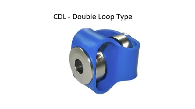
Stainless steel hubs are joined by a polyurethane double-loop body that absorbs shock, vibration, misalignment and axial movement. This is a robust choice for heavy industrial machinery, and the only PCA series rated to 3,000 RPM with published inertia (0.1 kg·cm²). Available with imperial 3/8" and 1/2" bores. Fastened with four M4 set screws.
CST standard couplings: low-cost general purpose
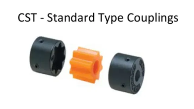
Zinc hubs with a polyurethane insert give a simple, economical coupling for speed feedback and general monitoring where very high accuracy isn't needed. Low torsional stiffness (3–12 N·m/rad) means it absorbs vibration well but is not suited to precision positioning.
Specification comparison
Size and performance
| Series | Bores (mm) | Torque (N-m) | Stiffness (N-m/rad) |
| CSR bellows | 6 ~ 12 | 0.5 ~ 1.3 | 110 ~ 240 |
| CSS bellows | 6 ~ 12 | 1.0 ~ 2.0 | 150 ~ 330 |
| COL Oldham | 3 ~ 12 | 0.7 ~ 4.5 | 31 ~ 280 |
| CJW jaw | 10 ~ 15 | 12.5 ~ 16 | 130 ~ 220 |
| CDL double loop | 8 ~ 12.7 | 1.5 | 25 |
| CST standard | 6 ~ 12 | 0.5 ~ 1.5 | 3 ~ 12 |
Misalignment limits
| Series | Offset (mm) | Angle (°) | Axial (mm) |
| CBR / CSS | 0.1 ~ 0.15 | 1.5 ~ 2 | up to +0.6 / -1.8 |
| COL | 1.0 ~ 2.5 | 3 | Nil |
| CJW | 0.08 | 1 | Not stated |
| CDL | Not stated | Not stated | Accommodates |
| CST | 0.2 | 2 | Nil |
Full dimensions and every bore combination are in the PCA Encoder Couplings data sheet, which you can download by clicking on the Related Products link below.
Quick selection guide
| If your application needs.. | Choose |
| Highest accuracy, zero backlash | CBR bellows |
| Accuracy plus corrosion resistance | CSS stainless bellows |
| Large parallel offset | COL Oldham |
| Electrical isolation | COL Oldham or CJW jaw |
| Shafts up to 15mm or higher torque | CJW jaw |
| Shock, vibration or heavy industrial duty | CDL double loop |
| Imperial shafts (3/8", 1/2") | CDL double loop |
| Low-cost speed or general feedback | CST standard |