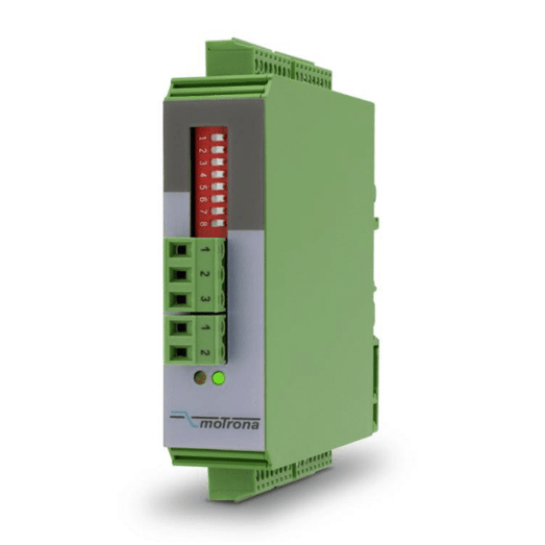
Motrona GV210: Incremental Encoder Signal Converter, Splitter and Switcher
Many machines need one encoder signal to go to more than one place, or need the signal changed before a drive or PLC can read it. The Motrona GV210 does three of these jobs in one compact DIN-rail module:
- Level converter: changes HTL (10–30 V) signals to TTL/RS422 (5 V), or the reverse
- Encoder splitter: sends one encoder signal to two devices at once
- Encoder switcher: lets one controller read either of two encoders, selected by a 24 VDC control signal
Need help finding a suitable encoder ? Send any questions through our contact page here,
or call us directly on 1300 236 467
Both inputs and both outputs can each be set to HTL or TTL/RS422, so the same unit can convert levels and split or switch the signal in one step.

Encoder level converter (HTL ↔ TTL/RS422)
Encoders and the equipment that reads them don't always use the same signal level. An older machine may have a 24 V push-pull (HTL) encoder, while a new servo drive or motion card only accepts 5 V RS422 line-driver signals. The GV210 converts between the two:
- HTL 24 V push-pull to TTL/RS422 5 V
- TTL/RS422 to HTL
- One HTL level to another, for example 10 V to 24 V
This lets you keep an existing encoder when you upgrade a drive or PLC, instead of replacing the encoder and re-mounting it on the machine.

Encoder splitter (one encoder, two outputs)
A common need is to send one encoder's signal to two devices. For example:
- a variable speed drive (VSD) for closed-loop speed control, and
- a PLC or HMI for position readout.
Wiring one encoder directly to two inputs can load the signal and cause missed or extra counts. The GV210 buffers the signal and gives two separate outputs, so each device gets a clean signal. Each output can be set to a different level, for example RS422 to the drive and HTL to the PLC.

Encoder signal switcher (two encoders, one controller)
In switcher mode, the GV210 connects either of two encoders to a controller. An external 24 VDC control signal selects which one, and the changeover is contactless and bounce-free. Example applications:
- Two encoders, one display: show either encoder on one display, selected with a 24 V switch.
- One encoder, two machines: a speed-synchronised conveyor encoder feeds machine A or machine B, each with its own PLC, depending on which line is running.

GV210 key specifications
| Specification | GV210 |
| Functions | Level converter, splitter (dual output), cross switcher |
Inputs | 2 × A, /A, B, /B, Z, /Z (each set to TTL/RS422 or HTL) |
Outputs | 2 × A, /A, B, /B, Z, /Z (each set to TTL/RS422 or HTL) |
Max. input frequency | 1 MHz (differential), 250 kHz (single-ended) |
| Power supply | 12–30 VDC, reverse polarity protected |
Encoder supply | 5 VDC auxiliary output |
Switching | Contactless, bounce-free, by remote control signal |
| Mounting | DIN rail, 22.5 mm wide housing |
| Connections | Screw terminals, 1.5 mm² / AWG 16 |
Full specifications in the datasheet, use the product link below to download.
Choosing the right encoder interface
- Level converter only: one encoder, one device, different signal levels.
- Splitter / buffer: one encoder, two or more devices. The GV210 gives two outputs. For more outputs, see the [Motrona GV204 pulse splitter] [link] or [other model] [link].
- Isolated splitter: use one when devices are on different earths or cable runs are long, to prevent ground loops and noise. [Editor: confirm with the datasheet whether the GV210 is galvanically isolated, and name your isolated alternative.]
- Switcher: two encoders, one controller, selected by a control signal.
Not sure which you need? Send us your encoder model and the devices it connects to, and we'll recommend the right unit.
Frequently asked questions
Can I connect one incremental encoder to two PLCs or drives? Yes. Use an encoder splitter such as the GV210. It buffers the signal and gives two separate outputs, so neither device loads the other and both get a clean signal.
Can I convert an HTL encoder signal to RS422 or TTL? Yes. The GV210 converts 10–30 V HTL push-pull signals to 5 V TTL/RS422, and back again. Each input and output is set separately.
What is the difference between an encoder splitter and an encoder switcher? A splitter sends one encoder to two devices at the same time. A switcher connects one of two encoders to a single device and changes between them on a control signal. The GV210 can do either.
What frequency can the GV210 handle? Up to 1 MHz with differential (A, /A, B, /B) signals and 250 kHz with single-ended signals.
Talk to PCA Encoders
PCA Encoders supplies Motrona signal converters, splitters and encoder accessories from offices in Melbourne, Sydney, Brisbane and Perth. Call [phone number] or [request a quote for the GV210] [link to https://www.pca-aus.com.au/motrona-gv210], and our engineers will help you choose the right setup.