How to Install Hollow Shaft Encoders
A hollow shaft encoder mounts directly onto the shaft it measures, so it needs no coupling and very little space. Getting the installation right is what makes the encoder last. The housing has to be stopped from rotating, but it must still be free to follow any small movement in the shaft. This guide explains how to do that, and how to set the zero position on absolute encoders and on incremental encoders without a zero-set input.
Need help installing an encoder ? Send any questions through our contact page here, or call us directly on 1300 236 467
Why a hollow shaft encoder needs a torsion arm
PCA’s hollow shaft encoders are designed to carry their own weight on the driving shaft. They don’t need a bracket or a rigid mount.
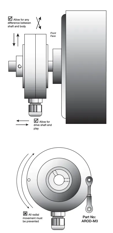
What they do need is a simple torsion arm to stop the housing turning with the shaft. The arm should stop rotation only. In every other direction it must stay flexible, so it can absorb any runout between the shaft, the equipment frame and the encoder housing.
If the housing is held rigidly, every bit of shaft wobble and misalignment is forced into the encoder’s bearings. Overstressing the bearings will seriously shorten the encoder’s working life.
Choosing a torsion arm
The torsion arm fits between the mounting hole on the outer edge of the encoder housing and a fixed point on the equipment frame. There are three common ways to do this.
Thin stainless steel strip
A Z-shaped strip of thin-gauge stainless steel, around 0.5 mm thick, is stiff against rotation but flexes easily in other directions. It’s a simple, low-cost choice for many installations

Rod end with ball fixing eyes
A rod end with a ball joint at each end makes an excellent torsion arm. The ball joints let the housing move freely in every direction except rotation. The threaded rod also gives fine (vernier) adjustment, which is ideal for aligning the electrical and mechanical zero. PCA supplies a ready-made rod end arm, part number AROD-M3.
Pin and groove
Some hollow shaft encoders have a groove in the front face. A pin fixed to the equipment frame sits in this groove and stops the housing rotating. The pin can still slide in the groove as the shaft moves.
Allowing for shaft runout and end play
No shaft runs perfectly true. Bearing clearance, thermal expansion and machining tolerances all cause some radial runout and some axial end play. Whichever torsion arm you use, check that:
- the housing can move with the shaft in the radial and axial directions
- the arm isn’t preloaded or bent when it’s installed
- the hollow shaft clamp is tightened onto the drive shaft, and the housing itself isn’t clamped to anything
Aligning electrical and mechanical zero
Absolute encoders, and incremental encoders without a zero-set input, have a fixed electrical zero. To line it up with your machine’s mechanical zero, the encoder body has to be rotated on the shaft until the two match.
Choose a torsion arm that allows this adjustment. The rod-end arm is ideal, because lengthening or shortening the rod turns the housing by small, controlled amounts.
Common installation mistakes
- Rigid brackets. Bolting the housing directly to the frame transfers all runout into the bearings.
- A stiff or over-tight torsion arm. The arm must stop rotation only. It shouldn’t stop the housing from moving with the shaft.
- Ignoring end play. If the arm can’t follow axial movement, it loads the bearings every time the shaft shifts.
- No zero adjustment on absolute encoders. A fixed arm with no adjustment makes it hard to set the zero position.


