Encoder Cable Length Limitations, Precautions & Solutions
The speed and position signals of rotary encoders often need to be transmitted over long distances that are questionable for reliability.
The distance from the point of “pick up” to the controller (PLC, VSD, or display) needs to be considered and cannot be an indefinite length. Certain measures can be taken to avoid signal problems.
Problems caused by cable runs that are too long can present intermittently or may only present after some time, as interference conditions change, or electronic components such as capacitors age.
Steps should be taken at the design stage of a system to avoid such problems.
Incremental Encoders Cable Distances
It is possible to transmit and successfully read incremental encoder pulses over distances of 100m or longer, if ideal conditions are met.
Important factors to consider include:
- Using high-quality, individually shielded twisted pair cables with a thick gauge copper core for low resistance, and designed for low capacitance and inductance if possible. Higher resistance leads to greater voltage drop, resulting in lower encoder pulse voltage at the receiving end.
- The path that the cable follows avoids high voltage cables or any electrically noisy systems.
- Always use a quality shielded cable (steel braid preferred), and make sure that the shield is grounded.
- Should you experience electrical noise induced from Variable Speed drives cable runs, make sure these cables are well screened.
- It is strongly advised that all 6 encoder channels are used, A, B, O, /A, /B/, /O. With long cable runs, the inverted, complement, or NOT channels should be physically wired and enabled in the controller. These channels serve as a reference to boost the receiver’s immunity against signal degradation and noise interference.
- When wiring for differential signal (A,/A,B,/B,Z,/Z), A and /A should be wired using one twisted shielded pair; B and /B should be in a second pair, etc. Failure to use complementary pairs (say, using A and B in a twisted pair) will reduce noise immunity significantly.
- An HTL signal is preferable. The voltage of these signals can typically be between 4 ~ 30V. If possible, try to use a high voltage such as 24VDC. 5V is not suitable for longer encoder cable distances.
- It may help to use an external switch mode power supply, as the controller’s onboard power source may not have enough power to cover the long cable distance.
- If the application allows it, an encoder with a lower PPR would be beneficial, especially if the application RPM is high.
Selecting the right cable for your encoder application
ADM recommends the following Encoder Cables:
- FLEX-06CORE
- FLEX-08CORE
What makes these cables suitable for encoder use?
- Twisted pair cables
- Low resistance, low capacitance
- High quality screening, tinned copper braid is far superior to a foil jacket layer.
- PUR outer insulation is oil and heat & cold-resistant, and more resistant to mechanical abrasion than PVC.
- Energy Chain rated for use on moving applications where the cable will be continuously flexed.
If the optimal conditions are not met, or even longer cable runs are required, a few electronics solutions can be considered.
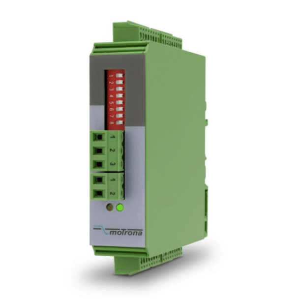
Solution 1
Encoder Signal Booster:
If you can mount the encoder halfway along the cable route, the Motrona GV210 encoder signal conditioner can retransmit the signal with renewed signal strength & clarity.

If the GV210 is not used as a “pass through” device, it can be used to convert HTL voltage levels to TTL and vice versa.
Solution 2
A fibre optic cable solution is the best for total reliability and immunity from noise and interference over long distances of up to 3000m.

Motrona LW215

Motrona LW216
German manufacturer, Motrona developed the LW215 encoder signal fibre optic transmitter and LW216 receiver to solve these problems.
Absolute Encoder Signal Distances using FieldBus or Ethernet Protocols
Industrial Ethernet protocols such as EtherNet/IP, Modbus TCP/IP, ProfiNet and EtherCAT have a distance limit of around 100m.
Again, consideration in cable quality and route can help maximise the permissable distance to the encoder and minimise reliability issues.
Encoders using more traditional fieldbus protocols such as serial RS485, Modbus RTU, CANbus can run longer distances of between 500m and 1km.
However, these distances are typically achieved by reducing the signal speed or Baud rate to a low value, which is often not suitable in a motion system that requires any level of tight control or precision.
Absolute encoders that have a 4-20mA loop signal can be used for cable runs of up to 500m, or possibly longer, and offer fast response times, whilst being relatively noise immune.
The products mentioned above are available from stock in PCA Encoders’ Australian warehouse.
To consult with our expert engineers who are readily available to advise on any of your encoder feedback concerns please contact PCA Encoders.
IS THIS INFORMATION USEFUL?
If so, why not share it with your peers and colleagues. Simply click on the blue LinkedIn share icon below.