Automated End of Production Line Encoder Testing
The Encoder-LAB02 is a dual-purpose instrument for quadrature incremental encoders with square wave outputs..The Encoder-LAB02 provides users with useable insight quickly and reliably both as a tester for encoders and from the encoder simulation modes within the unit itself and can provide greater detail n connected to a PC to utilise the EncoderLAB software.
EncoderLab Simulation Modes.
The encoder provides a simulation function that gives users the ability to test other instruments and systems that require encoder signals without having the mechanical means that typically generate those signals. The simulation functions will cater to users with two modes, Continuous mode, and the 1 Cycle Mode (otherwise known as “Burst Mode”).
Continuous Mode.
In Continuous mode, the output provides a continuous train of pulses until the user presses the stop button. The user will set the frequency of the A and B channels, and the Z channel is produced based on the PPR parameter, which is also set by the user. This can be used to simulate an encoder attached to a motor running at a specific speed.


Cycle Mode (Burst Mode).
The cycle mode simulates an application for a wheel or roller, where users may need to determine position, length, or distance and a certain pulse count may trigger an action by the control system. A user can achieve this by running the function and running a pulse count within this mode, simply hitting “run” on the function allowing the simulator to provide a burst of “x” pulses, and hitting the “run” button again to complete the simulation.


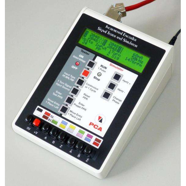
Encoder Tester.
The encoder tester operation gives the ability to check the parameters of the encoder attached to it. The EncoderLAB-02 will count the number of A and B pulses per Z pulse. This ratio will provide a reading of the PPR of the encoder under test. Other parameters such as the frequency, RPM, and even the supply current of the encoder is reported on the unit LCD screen.

Connecting the instrument to a PC and running the EncoderLAB software gives the user access to more information about the encoder being tested. Additional information includes the high-to-low ratio (duty cycle) of the A and B pulses and the measured phase difference between the 2 signals. A graphical representation of the waveform is also shown, based on the collected data.

Printing an encoder test report is also available when connected to a PC.

Auto-Test Function and the Encoder-LAB-Relay01
A recent update to the ENCODER-LAB02 is the addition of the Auto-Test Function. This new mode takes measurements of standard encoder parameters (see previously discussed encoder tester parameters), and the measurements are compared to user-defined tolerance criteria. At the end of the test, the screen will display “PASS” if all measured quantities meet the respective criteria, and “FAIL” otherwise.

, EncoderLAB-02 LCD screen after an AUTO TEST (right)")
The Auto-Test Function can be set to run just on the “forward” rotation (i.e. 1 set of measurements only), or both “forward” and “reverse” rotation (1 set of measurements taken during the forward motion of the encoder, and another set of measurements taken during the reverse motion of the encoder). If both directions are required for the test, a manual process of reversing the test motor is required to proceed. For this, PCA Encoders has designed the ENCODER-LAB-RELAY01. This is an accessory board developed for triggering the forward and reverses motion of the test motor. The Encoder-LAB02 will interface with the ENCODER-LAB-RELAY01 via the DB9 connectors present on both units.

Inside this black box are 3 relays:
- Relay 1 will be energized when the ENCODER-LAB02 is testing in the forward direction
- Relay 2 will be energized when the ENCODER-LAB02 is testing in the reverse direction
- Relay 3 will be energized when there is a fault during testing
Relays 1 and 2 can be used as inputs to the motor drive to tell it to move forward or reverse.
Alternatively, they can be wired up directly to alternate the polarity of a low-power DC motor to control forward motion and reverse motion.


Aside from the main box, the Encoder-LAB-Relay01 comes with the interface cable to connect to the Encoder-LAB02, as well as a barrel plug splitter, so that the Encoder-LAB-Relay01 can be powered (via the plug splitter) from the same power supply as the Encoder-LAB02.
Would you like to know more?
To learn more about the Encoder-LAB02 or the Encoder-LAB-Relay01, please contact our PCA Encoders team here.